Impressum/Note Privacy
|
Pages by Andreas B. M. Hofmeier |
|
Impressum/Note Privacy |
|---|
|
http[s]://www.abmh.de/en/papers/lsbu/fyp/doc/FYPFinalReport.HTML/index.html |
|---|
PDF Version (best view)
LaTeX SRC
Entire Project and Appendices
| Submission Date: | 26.04.2005 |
| Student ID: | 2406108 |
This report is written in the author’s own words and all sources have been properly cited.
Author’s signature:
Acknowledgements
I would like to thank my supervisor, Dr. Shuwo Chen, who supervised this project and was always ready to answer my questions.
Thanks are also given to other people from London South Bank University and the University of Applied Science Bremen, who offered their assistance to me while doing this project. Dr. Chris Merridan, the technical assistant and Mr. Jianzhong Shang, who supported me in dealing with the robot experiment. Dr. Thomas Risse who helps me to organise of my overseas-term. My German class mates stood on my side with advice and encouragement. All peoples who provided help in form of materials such as free software (GNU Linux), free documents (web-sites), articles, and books.
Abstract
This report describes the final year project done by Andreas Hofmeier. The project is aimed to develop the software tool for the communication between robots and computers on the Internet to realise the remote control of robots via the Internet.
The feasibility study of controlling robots on the Internet was re-examed, identifying the certain restrictions affecting the communication and hence control on the Internet. One conclusion has been drawn that the time delay is the most important restriction is caused by the local network but not by the Internet. Several approaches to the restrictions were studied and a promising method, the line monitor, was developed.
A software platform in form of a library for GNU Linux was developed to provide the necessary tools for implementing robot control on the Internet. The platform is successfully used to control a Cartesian robot in laboratory test.
The results have proven that design methodology for the project are correct and the theoretical results will benefit future development.
The aim of the project is to develop a software platform on GNU Linux systems (in the form of a library) for the communication between a server and robots to realise remote control of robots over the Internet. The communication between robots is allowed as well.
The objectives have been met and the deliverables include,
Robots become more and more important because the technical progress allows economic and useful applications. Controlling robots over a short distance with cables or wirelessly is quite popular, but more often robots need to be controlled at a remote site far away from the scene. For example a robot as security guard or a pizza-robot is operating at home while controlled from the office. To meet this demand a communication network is required.
One of the most flexible and economical solutions is to control robots on the Internet that works packet-oriented. All data have to be fragmented before it can be transmitted. The transmission process on the Internet can be compared with the postal service (Ball et al. 1999). “The packet should be there within two days” is a possible answer to the question how long the delivery takes. This little word “should” is the problem. It should, but there is no guarantee. If many packets are handed in, it may take a week or more time to deliver them. The Internet has the similar problem. Even if a packet does not need a week to reach a recipient, it is still difficult to predict a delay time because huge amount of users are at random using the resources on the Internet. Therefore as a user of the Internet, a controlled robot may encounter a statistic time delay. (Elhaji et al. 2000).
Through this project the feasibility of controlling robots remotely over the Internet was studied. A software platform on GNU Linux which provides this functionality was developed.
This platform in form of a network library provides the tools to utilise the Internet as a communication link to control a robot. An example of using the network library is given by a simple demonstration on a real robot. The demonstration includes a user interface, a simulator, and an interface to the robot.
The analysis has shown that under certain circumstances it is possible to actually control a robot on the Internet. One of the possibilities is to observe the network connection and initiate appropriate actions when the line (connection) becomes unusable for the remote control. This idea was adapted from Andreu et al (2003) and implemented. In this report it is called the line monitor.
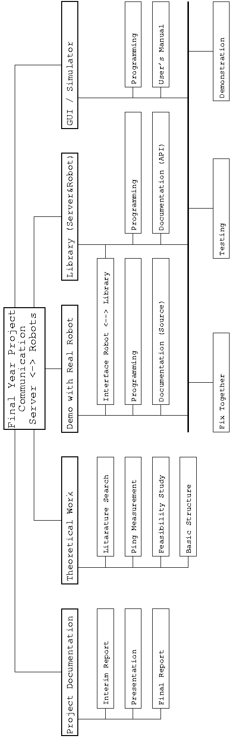
The report is structured in the following way: the first two sections define the aim, the objectives, and the deliverables of the project. The next section introduces the technical background. After this the technical approach will be explained in detail. The results of the analysis and the tests are given in the next chapter named “Results and Discussion”. The conclusions and recommendations for further work are given in Chapter 5. After that the Bibliography is listed. It is followed by details about the planning of the project compared with its actual realisation. The last parts of the report are the appendices which include the software and its documentation (user’s manual and application programmer interface).
Han et al (2004) distinguishes between three modes to control a robot which were adapted. This three points are extreme examples only. A robot in the “real world” will be somewhere between those extreme points. This depends highly on the application.
Within this control mode the hardware is controlled at lowest level over the network. There is no intelligence or data processing on the robot’s side.
For example: the robot receives a bit stream which represents its outputs. The robot receives a package of n bits analogous to n output-bits. These outputs can be simple actors which can only be switched on or off (one bit) or complex solutions with digital-to-analogue converters which are controlling a DC-motor (maybe 12 bits).
This mode requires strict time constraints because the controlling is time based. If the robot should move one meter in a direction the corresponding motor for this direction has to be switched on for exactly the time which is necessary to cover this distance. If the motor is switched on longer the robot will cover a greater distance and vise versa. The engines has to be switched “in time” but this is almost impossible if the time for transmitting a bit (or a package if more than one motor has to be controlled) varys from one command to the next one. If the time-delay would have been constant, it could be simply subtracted in the calculation.
Another problem occurs if the connection breaks down. When the robot receives a “start moving” command just before the connection fails it may move until the battery is empty. This can be a hazard if, for example, the robot hits someone.
This control mode controls the robot on a much higher level. For this reason more intelligence is needed on the robot’s side.
A target is transmitted to the robot. The robot has to evaluate this target and
calculate the appropriate action to reach it. The target can be transmitted in relative
( x, y) or in in absolute (x, y) coordinates (In this case it is assumed that the robot
has two degrees of freedom – can move in two dimensions.) In the first case the robot
has to calculate which actors have to be switched on and for how long to cover the
given distance in the right direction. In the second case the robot has to know its
current position to calculate the x and the y which can be used to move to the
target.
x, y) or in in absolute (x, y) coordinates (In this case it is assumed that the robot
has two degrees of freedom – can move in two dimensions.) In the first case the robot
has to calculate which actors have to be switched on and for how long to cover the
given distance in the right direction. In the second case the robot has to know its
current position to calculate the x and the y which can be used to move to the
target.
The calculation of x and y may include considerations like:
In this mode the time constraints are not as strict as in the direct control because the robot will stop moving if the target is reached and no new targets are receive in time. Normally hazards only occur if something is moving or is “in action”.
Within the Job Scheduling Mode a whole sequence of targets or jobs is transmitted to the robot at once.
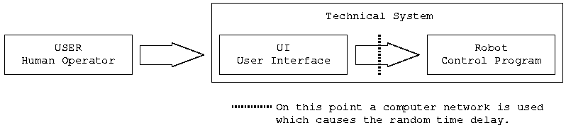
To be able to “teleoperate” something (for example to control a robot from far away) at least three levels of data-processing are necessary. These three levels are the human operator, the User Interface (UI), and the robot control program. They are illustrated in figure 1.
In these days the requirement of multi-functionality becomes more important. The robot should be as flexible as possible to be used in a wide spectrum of applications.
To use a robot for a new application the program which controls it has to be changed. As discussed above this program is made up of three components. (If it is assumed, that there is some kind of “program” in our brain.)
In case that the “technical system” is very primitive it may be enough to train the human operator to do other things with it. An example could be a simple remote control of a crane which switches actors remotely.
An important improvement of our technology today is that it helps us to perform our tasks. The time of a human operator is valuable and should not be wasted in doing things which can be done by a computer. Many calculations can be processed much faster and more accurate by a computer than a human.
The consequence of this is that it may not be enough to train the human operator to do new things with the robot. In this case two components are left: The GUI1 (Server) and the robot control program.
One solution is to keep the robot control program as simple as possible and transfer all intelligence into the GUI (the Server). In this case the direct control is in use. As discussed this can be a problem because of safety considerations. If the network link breaks down no server or human operator can stop the robot. There must be some processing on the robot’s side. At least an emergency stop function has to be implemented. This solution makes it possible to change the behaviour of the technical system only by changing the server/GUI side. This can be an advantage.
On the other hand it is possible to perform one part of the processing on the robot’s side. This moves the classification of the system closer to the supervisory control. The GUI/server transmits a job or a target to the robot and monitors its execution. It might be necessary to change both, the GUI/server and the robot control program in order to change the behaviour of the system. Advantages of this solutions are: distribution of processing work on both sides, probably less bandwidth requirements, and a possible gain in safety.
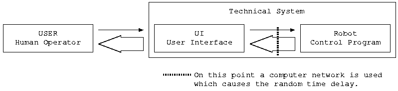
Another important issue needs to be considered: the feedback. This is the difference between operating or affecting something and controlling it. Affecting means to do something without getting a response. There is no guarantee that everything happens the way as it was intended to happen. Controlling applies a feedback which closes this (response-)loop. For example, it can be seen what the robot does. In this case it is likely that the bandwidth of the feedback connection is much bigger than the control connection because of the video data. Figure 2 illustrates this example. Unfortunately these meanings are often confused. In this report the word “controlling” is used for both.
|
The term “real time” is used for systems which have to complete a task in a certain time. This time depends on the application but it can be said that the (reaction-)time must be short enough to perform an in-time control of the environment. In this case the transfer of data over a network has to be finished within a certain time-limit.
Bandwidth describes how much data a network is able to transfer in a certain time. The time delay will increase if more data is transmit because the data has to be buffered until the line is free. If continuously more data is transfered the network can no longer transfer all the data without loosing some of it.
Both terms are interdependent. This will be explained in the following section.
Before it is possible to explain what the problem causes it is necessary to provide an overview about “how it works”. If detailed information is requested please refer to a textbook, for example, Forouzan (2001) from which this overview was condensed.
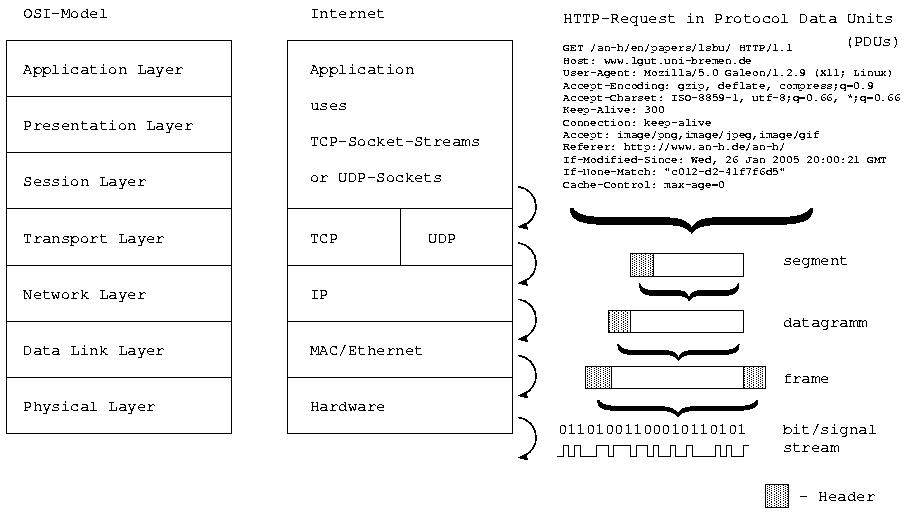
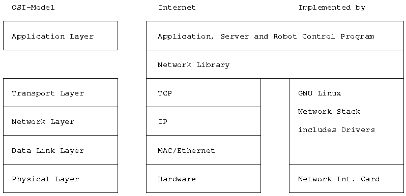
Figure 3 shows an overview of the different levels of data-processing which have to be
passed before a communication is possible. The diagram illustrates these levels on a
Hyper Text Transfer Protocol (HTTP) request. Those requests are generated if a
web-page is opened. In the case of the example it was
http://www.lgut.uni-bremen.de/an-h/en/papers/lsbu/. The OSI-model (left
hand side) is a general description of the network layers. These OSI layers assigned to
real layers which are used in the Internet. The right hand side lists the different types
of protocol data units (PDUs) (packages) which are created by each layer.
Each layer adds management information (a header) which are shown as
gray extension. In this report the general term package is used for different
PDUs.
To understand the idea behind these levels of layers it can be compared to telling someone a long story who is on the other side of the world. The narrator (the application) starts writing it and gives the script its secretary (the transport layer, TCP). She knows that the postal service accepts letters up to a maximum of 80g. For this reason the story has to be segmented into pieces which fit on less than 80 grams of paper. In order to make it easier to recombine the story on the other side of the world, supporting information like a segment-number is added to each letter. This letter is given to the next secretary (the network layer, IP). In this step the letter will be placed in an envelope. This envelope on which the source and destination address is written will be handed in to the nearest post office (the data link layer). Within the post office the letter will be packed into a bag which is transported to another post office. This office may resort the bags and send it to the following post office. This process (which can be compared with the routing and transferring data over a line [physical layer]) will be continuing until the letter reaches the mail box of the receiver. Then the reverse process takes place.
The problems which arise from this process are: the system must work transparently. That means that the higher levels do not know what the lower levels are doing. For this reason the behaviour of the lower levels may vary. An example for this is a replacement of one secretary.
The same problem occurs during the transport. There is no guarantee that the letter will always take the same route. It is unknown which way a letter will take. This depends on the environment and on the network load or utilisation. If, for example, an earthquake destroys a road, the mail must take another way. The workload of the system may change faster than the environment. During the rush-hour it takes longer to cover a distance than on a “normal” daytime. This can be compared with school hours – all students using the network. This both phenomena cause the random time delay.
The next problem arises from the way in which the physical layer transmits data. Ethernet is used in most of the end-user networks of the Internet. Carrier Sense Multiple Access with Collision Detection (CSMA/CD) is in use within Ethernet. This protocol tries to broadcast when nobody else is sending data. If the network load increases it becomes harder to find a gap to send the data. Because of physical limitations (transmission speed) computers do not recognise fast enough if data is sent and start sending by them selfs. This causes collisions. Data is destroyed and has to be sent again. Because of this the delay increases with rising workload. These both are reasons for the unpredictability of the transport time. This is not applicable to modern switching networks. (Fairhurst 2004)
To use the high-level Transmission Control Protocol (TCP) or the User Datagram Protocol (UDP) to control robots is not the most efficient way. It is possible to bypass the official transport layer by replacing it with an own protocol that is optimised for real time traffic. Liu et al (2004), for example, developed the “trinomial protocol”. This is a semi-real-time-protocol. It works much better than the TCP or UDP but it cannot change the lower levels. These levels have to be used if the Internet should transport the data. They are prescribed by the Internet itself as a standard.
Another possibility, which was adapted from Andreu et al (2003), is to observe the network-connection and take appropriate actions if the connection becomes unusable for the purpose of remote controlling. This strategy assumes that the network is normally usable for the job. Without any further actions this method is not well suited for direct control. Instead it is very suitable for an additional usage.
Andreu et al (2003) explored the possibility of using a buffer or a stack as a “Delay Regulator” to smooth up the random component of the transport delay. This is done by delaying the data on the receiver side (buffer) in a way that the overall delay stays constant. For example, if one command has to be processed in one second, one command per second has to be ready for processing on the robot’s side. Assuming that the maximal time delay for the transmission is 5 seconds, the sender starts transmitting 5 seconds before the robot starts executing commands. All data which is received earlier will be stored in a buffer. If the sender sends one command in one second, the robot reads one command a second from the buffer, and the maximal time-delay does no exceed 5 seconds, the commands are constantly delayed by 5 seconds. This is the way to suppress the random component of the time delay by extending the delay to a maximal value.
This solution is suited to be used for direct control but has the disadvantage that the transmission takes longer than necessary. If everything works well all commands are delayed by the same time. It makes sense to combine this solution with a line-monitor to take appropriate actions if the maximal delay was exceeded.
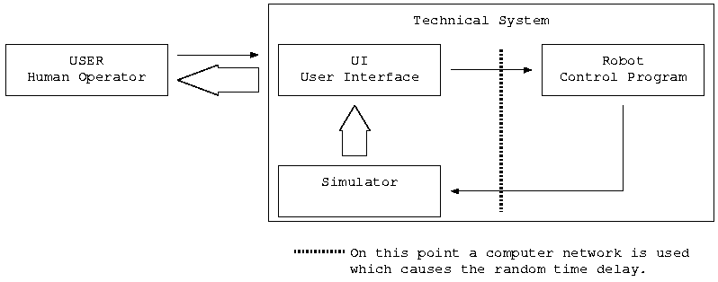
One idea to fit a robot-control-system into existing bandwidth constrains is to prevent the large bandwidth-consumption of the video-data-stream by using a simulator. This simulator simulates the environment of the robot on the GUI/server side. Figure 4 gives an example of this. (Belousov 2004; Han et al. 2001)
|
This solution makes a simulation of the reality necessary. However, the best simulation is still just a simulation and not reality itself. For this reason reality and simulation may differ. Maybe the physical attributes of an object are calculated in a wrong way or the feedback is not accurate enough and an object is pictured in an other place than it really is. This can be a safety risk which has to be considered.
According to the British Standard (1992) Industrial robots – Recommendations for safety, a single point of failure must not cause any hazards. For this reason it is very important to stop the robot if the network link breaks down. The technique of monitoring the line is well suited to this application.
To explore the feasibility of using the Internet for remote control of robots the ping measurement was conducted. Over one week the round trip time (RTT) to the destinations was measured every minute. The gathered data was analysed statistically. A second ping measurement was conducted to proof the assumption that an overload of the local network causes the majority of the time delay.
Ping is a tool which sends ICMP2 echo requests to the destination. The destination computer echos the request package (sends it back to the sender). The initiator of the ping request measures the time between sending the ping and receiving its echo. This is the RTT, the time which is necessary to transfer data to the destination and back. The additional processing time on the destination is immanent. This value can be neglected because it is very short in comparison to the transfer time. The fault caused by neglecting this time minimises when the whole ping time increases.
By default a ping package has an overall size of 84 bytes and contains the following parts: the IP header (20 Bytes) which specifies the source and target (IP) address and some network management information. The ICMP header (8 Bytes) contains a sequence-number, a checksum, and an identifier. The last part is the data part (56 Bytes) which contains a timestamp and filling-bytes. (Forouzan 2001; Kozierok 2004; Berkeley 1996) Over one week 10080 pings were sent which correspond to 846720 Bytes or 826 kByte in one direction per destination. The same amount of data was sent back.
The pings were sent from the author’s private server which is located in the ’Schulzentrum Utbremen’ a school in Bremen, Germany. It is connected through the local school network and the network of the University of Bremen to the Internet. This server was used because the network of the LSBU does not allow to send pings to external computers.
All distances were calculated by using Global Positioning System (GPS) coordinates. The short overview about GPS coordinates given by Guthrie (2004) was used. All GPS coordinates were obtained from Maptech (2005) except the Unisa one which was adapted from Kennington (2000). It was not possible to obtain any exact GPS coordinates from the servers which were utilised. Coordinates from the home city or near objects were used. For this reason the accuracy lays far beyond the GPS accuracy. In addition to this the calculation results are air-line distances and not the real lengths of the cable of the transmissions.
To calculate the distance the following steps needed to be performed. Calculation of the difference between the latitude of the destination and the latitude of Bremen and the difference between the longitudes. After this the Pythagorean Theorem was used to calculate the distance (the hypotenuse). The following formula was used:
distance = 
The destinations were selected to give a wide spectrum of distances. It was assumed, that the servers of the destination organisations were located within the organisation’s main building or near to it. It was not possible to locate a LSBU server which echoes pings. For this reason the LSBU did not become a destination.
|
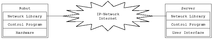
The first thing which was developed during this project was the basic concept. The network library provides the communication tools to the robot and to the server control program. A user-command takes the following way:
A user enters a command into the user interface of the GUI/server. The server control program reads a command from the user through the user interface, evaluates it, and sends it through the IP network (the Internet) to the other side by using the functions of the network library. The network library on the robot’s side receives the command and hands it over to the robot control program. The robot control program executes the command and controls the robot. The feedback from the robot follows this way in the other direction.
It is difficult to clearly distinguish between these levels. For example: there is no boarder between the GUI and the server control program in this project. In addition to this the robot’s side includes a GUI to. This GUI is implemented to simulate the assumed position of the robot. (In the real world at least an emergency stop key has to be implemented on this side.) The name of this program (robot and its GUI) is guirobot. The name of the server control program (and its GUI) is guiserver.
This communication has to be bidirectional. It must be possible to request data from the robot. This could be the acknowledgement for a command, obtaining data of the robots environment, and to monitor the robot.
The library was implemented on the free operating system GNU Linux because of the following reasons:
After the basic concept was clarified, the network library was implemented. The picture 5 does not show the entire truth. The network library by itself cannot transfer data through a network. It has to use lower levels.
During this project it was decided to used TCP for the data transmission. (Please refer section 2.5.1 on page 18.) The TCP and the levels underneath had to be implemented as well. This is not part of this project. Fortunately this was done before and it is now possible to use the implementation in the Linux-Network-Stack. In addition to the network implementation in Linux there must be some hardware in form of a Network Interface Card (NIC) and some network facilities like cables and hubs. Figure 6 gives an overview about the network layers which were used in this project.
The Linux kernel provides an interface in form of system calls to allow (user mode) programs to use its facilities. This section gives an overview about these system calls and the way in which they were used in this project. For more detailed information please refer to IBM (1995).
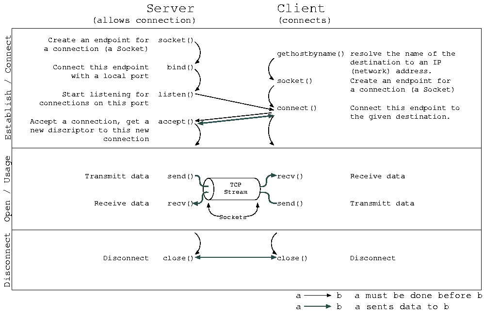
Figure 7 shows on outline of the steps which are necessary to establish, to use, and to disconnect a communication link – a TCP socket stream.
It is possible to accept() more than one connection on a bound port. For this reason it is necessary to distinguish between the socket which is bound to the port and those for incoming connections. For each new connection a new socket is generated and given back by this system call.
The communication (in Open / Usage) between both sides is duplex (bidirectional). The duplex mode (pseudo-, half-, or full-duplex) depends on the underlying network equipment. There is no prescribed order in which the sides have to call send() and recv().
The functions accept(), recv(), and send() will block3 by default if there is no connection to accept, no data to receive (no data was sent), or the sent-buffer is full (cannot absorb more data). This behaviour can be changed with fcntl().
For a detailed description of the system calls used please refer to the manual pages within the ’Linux Programmer’s Manual’.
To simplify the process of establishing a socket-stream connection the following functions were implemented:
In addition to this it was necessary to implement several sub-functions. All these functions can be found in the file src/lib/libcomm.c (appendices, section C.2 on page 175).
For a detailed description with parameters and return values of the listed functions please refer to the Application Programmer Interface (API) of the network library – libcomm – in the appendices section A.4 (page 161).
Please refer to section 4.3.1 (page 103) for details about the tests which were conducted to proof the correct behaviour of this functions.
Any data which is sent to a socket that is connected to a TCP stream will be transfered to the socket on the other side of this stream. The lower levels take care about the integrity of the data. The TCP monitors and corrects the order of the data and its integrity. This is important because data packages may follow different routes through the network or packages are lost and must be retransmitted. In both cases the packages need to be re-sorted on the receiver’s side. If the connection is broken due to a network fault, recv() and send() will return an error.
For control purposes often blocks need to be transfered. A block in this context is a unit of data. For example: target coordinates if form of two integers for x and y. If the size of the datablock is constant it is simple to receive or transmit it:
recv(fd, buf, n, MSG_WAITALL);
send(fd, (void *) buf, n, 0);
In this example fd describes the used socket, buf is a pointer to the block, and n the number of bytes to be sent or received.
MSG_WAITALL tells the function to wait until all n bytes are received. A problem may occur at this point: TCP is a stream protocol and acts in this manner. It guarantees that the bytes are in the right order. But it does not guarantee that if m * n bytes were sent, it will be received as m * n bytes. If, for example, two blocks with 10 bytes each were transmitted it is possibly received in one block of 20 bytes, two blocks with 5 and 15 bytes, or three blocks ...
This problem is caused by the transparency of the network stack. The higher levels do not know what the lower ones do. In addition to this TCP buffers incoming and outgoing data. Once the send() is called the behaviour of the network stack depends on many things. For example: buffer size, network load, and speed. On the receiver’s side all received data is stored in a buffer. recv() can load already received data from this buffer or it has to wait for some data to be received. This behaviour can be configured as mentioned earlier.
If different size blocks are possible it can be tricky to distinguish between two blocks because there is no way to know what block-size was used. To bypass this problem the block functions were implemented.
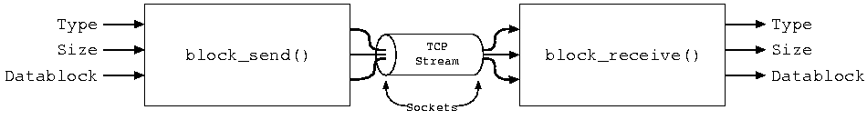
The block functions are transferring blocks according the following protocol. This list shows the transmitted parts and their order.
*) These are two byte-values used as a 16 bit integer. For this reason these values can vary in the range between 0 and 65535. A consequence of this is that the maximal size of a datablock is 65535 bytes. In addition to this the integer must be organised in the same way on both sides (GUI/server and robot). This can be tested be the test-program src/tests/test002integer.c (appendices, section G.2 on page 181).
In the programming language C data blocks are handled as pointers to the first unit (in this case a byte). There is no possibility to know how many units need to be processed if only the pointer is given. For this reason the block functions need to handle the size as well. Figure 8 gives a schematic of the basic block function.
Implemented functions:
In addition to this several subfunctions were implemented. All these functions can be found in the file src/lib/libcomm.c (appendices, section C.2 on page 175).
For a detailed description with parameters and return values of the listed functions please refer to the API of the network library – libcomm – in the appendices section A.4 (page 161).
Please refer to section 4.3.2 (page 106) for details about the tests which were conducted to proof the correct behaviour of this functions.
In this project it was decided to implement a set of functions to observe the network link (line). As explained in section 2.5.5 (page 25) this functions should be able to recognise if the network link becomes too slow to be used for remote controlling. In this case a function which takes appropriate actions (stop the robot) must be called.
The basic concept of these functions was adapted from ping. A data packet is sent to the other side which echoes it (sends it back to the original sender). The time between the “ping” launch and the arrival of its echo is measured. If this time exceeds a specific value a exception-function is called.
This implementation uses a TCP socket streams (not ICMP which is used by the original “ping”) to transmit one-byte messages. Because of the different layers which are in use (TCP, IP, and Ethernet) the size of the data package increases to 67 bytes (1 byte data, 32 byte TCP, 20 byte IP, and 14 byte Ethernet).
It can be helpful to distinguish between two levels of real time exceptions (timeouts):
The following functions were implemented:
In addition to this the exception-function is called if the connection breaks down, an emergency-stop-code was received, or an invalid answer (answer (echo) differs from request (ping)) was received. This function should run on the dangerous side (robot side) because the real-time-timeouts are more accurate than within the server function.
After one ping is echoed the function calls poll() to determine if the next ping arrives within wait-time plus soft-timeout. If the time-limit was exceeded it calls the exception function and repeats this procedure for the hard-timeout. The function repeats this until it is terminated.
In addition to this, the function linemonitor_thread() as “background”-part of the linemonitor()-function was implemented. All these functions can be found in the file src/lib/libcomm.c (appendices, section C.2 on page 175).
Problems with the implementation It was planned to provide the accurate round trip time (RTT) which was taken by the “ping”. The system call select() which waits for an event (for example incoming data) was used to realise this. This system call provides a possibility to request the time which the calling function was suspended. This functionality can be used to determine an exact value for RTT but it did not work. Maybe the function is not compatible with sockets. There was no direct hint about this in its manual page. For this reason the system call poll() was used instead. This system call does not allow to determine the exact time. It only states if the timeout was exceeded or not.
For a detailed description with parameters and return values of the listed functions please refer to the API of the network library – libcomm – in the appendices section A.4 (page 161).
Please refer to section 4.3.3 (page 107) for details about the tests which were conducted to proof the correct behaviour of these functions.
It is essential that the robot can only be controlled by an authorised person. It must not be possible for anyone else to give commands to the robot. For this reason it is necessary to implement some kind of authentication. This was done by including the following functions in the library: socket_md5auth(), getauthinfo(), and free_authinfo(). These functions were tested (please refer to section 4.3.2 (page 106) for details) but not used in the demonstration. Because of the last point it was forgone to describe the used protocol in detail.
For a detailed description with parameters and return values of the listed functions please refer to the API of the network library – libcomm – in the appendices section A.4 (page 161).
The mentioned functions can be found in the file src/lib/libcomm.c (appendices, section C.2 on page 175).
One objective of this project was to demonstrate the function of the library on a real robot. The following section describes how this was done.
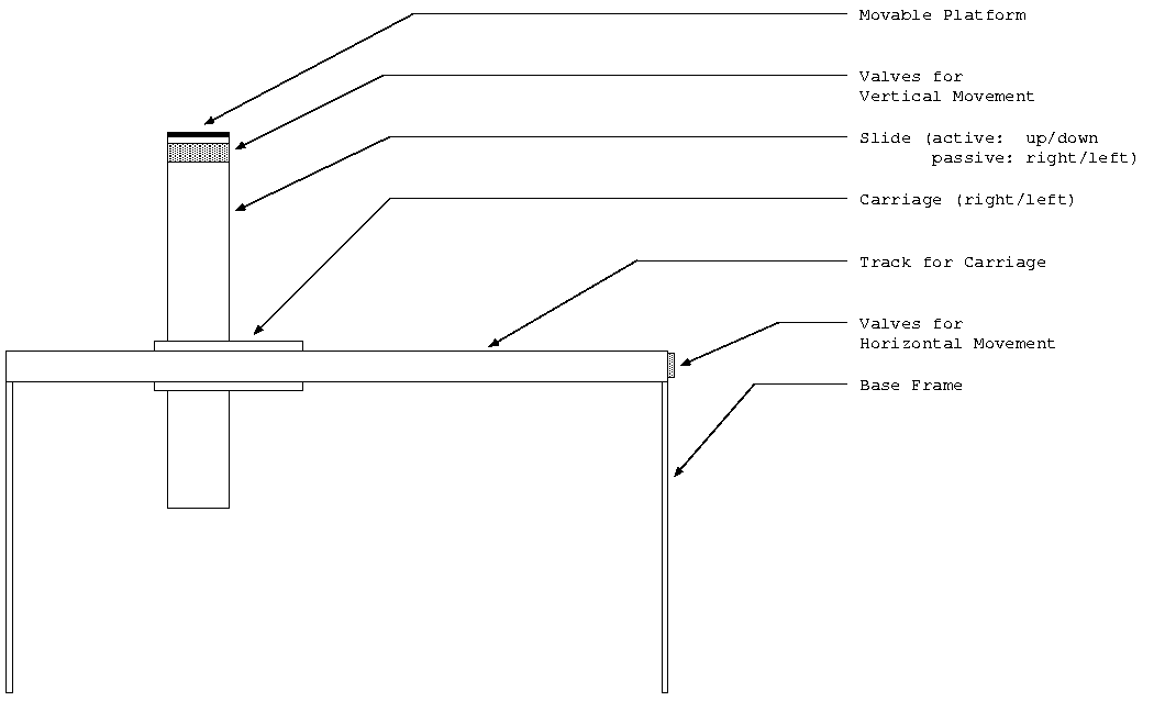
It was decided to use a Cartesian robot with two degrees of freedom. The robot itself is attached to a certain place but can move a platform in horizontal (x) and vertical (y) direction. The robot is driven by a pneumatic system which is controlled through electronic valves. There are four valves, one for each direction in both dimensions. To move the platform in a direction the assigned valve has to be opened. A valve opens at an operation voltage of 24V. The figure 9 gives a basic overview about the structure of the robot.
Unfortunately there was no interface, neither hardware nor software to control the robot with a Linux machine. Both was implemented in this project.
It was decided to use the parallel port to control the robot because only four actors needed to be switched on or off. A feedback from the robot was not intended. As mentioned earlier the valves to control the robot are driven by 24V. The valves consume about 100mA. This value was measured under operation at 24V.
The parallel port is neither able to deliver 100mA nor 24V. It works with 5V and can provide a few milliamperes. To connect the valves to the parallel port an amplifier is required.
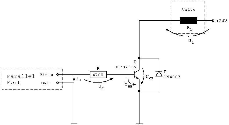
Figure 10 shows the amplifier circuit which was designed to control the valves by using
the parallel port. If the output of the parallel port is low (0 = 0V), UR is zero
either. If UR is zero, no current flows into the base of the transistor. The
transistor is closed, UCE  24V and UV lave 0V . The valve is closed. If the
output is high (1 = 5V), UR 4.3V , UBE 0.7V . The transistor is open:
UCE 0V and UV lave 24V . The valve is open. (Please refer to the following
calculations.)
24V and UV lave 0V . The valve is closed. If the
output is high (1 = 5V), UR 4.3V , UBE 0.7V . The transistor is open:
UCE 0V and UV lave 24V . The valve is open. (Please refer to the following
calculations.)
Calculation of the substitution resistor for the values. Used in the simulation. This value is only an approximation because of the inaccuracy cased by the power supply which generates UL and the measurement of IL.
RL = UL
IL = 24V __
100mA = 240
Calculation of R. Assumption: parallel port is operating (Hight = 1) and generates U0 = 5V ; 1mA is sufficient to open the transistor entirely.
R = U0-UBC
IB = 4.3V _
1mA = 4300
The calculated resistor value is not available (in E1 series). For this reason it was
decided to use 4700. The reverse calculation:
IB = IR = Iparallel-port = U0-UBC R = 4.3V _ 4700 = 0.91mA
This value is acceptable.
Worst case calculation: if the transistor generates a short-circuit between C and B, 24V on B. (Parallel port delivers zero, 0V.)
IR = Iparallel-port = - 24V__ 4700V = -5.11mA
The parallel port should not be damaged by this current if this happens.
The diode (D) is used to protect the transistor in case of a high self-induction voltage. The magnetic field in an inductive element depends on the current through it and vice versa. If an inductive load is switched off, the magnetic field (which does not disappear in an infinitely short time) forces a current. If the transistor is closed the current cannot flow and charges are divided. A high voltage is generated which can destroy the transistor. The diode allows the current to flow, no charges are divided, no problem occurs. The induced current flows in the opposite direction as the operation current. The diode allows the current only in this direction to pass. Because of this the transistor is not bypassed during normal operation.
The circuit as shown was built four times, one time for each valve. The main challenge in this part of the project was to built this four amplifiers small enough to fix them info the parallel port plug. Table 2 explains in which way the interface to the robot is wired.
|
Please refer to section 4.4.1 (page 108) for details about the tests which were conducted to proof the correct behaviour of this functions.
The software part of the interface was implemented to control the robot by using the hardware-interface.
According to Messmer and Dembowski (2003) the basis IO-port of the parallel port is by default located on the IO-address 0x378. The eight output bits can be directly accessed through this address. The following eight addresses can be used to control other features of the parallel port.
Normally these IO-ports are only accessed by kernel drivers. These drivers provide an interface (for example, some special files in /dev) to user level programs. User programs access the hardware only through the kernel. This is done due to security aspects. If any program could access the hardware directly, it could bypass the access permission management of the system. For example: copying private files by directly accessing the harddrive.
To be able to directly access IO-ports under Linux the program has to have the right to do this. This right is reserved for programs which run with root (system administrator) privileges. Those programs can enable the access to the IO-ports by calling the system-call iopl(3). After this was successful the IO-ports can be accessed by using inb() and outb(). inb(p) reads one byte from port p and returns it. outb(v, p) writes the value v to the port p. (Linux Programmer’s Manual)
To prevent collisions between the software interface and conventional Linux drivers these drivers have to be unloaded:
The software interface calculates the x and the y on the basis of given target
coordinates and the stored position. The interface has to remember the last
coordinates of the robot’s platform because there is no feedback from the
robot. There is no possibility for it to request the current position of the
platform.
To know the start position of the platform the interface moves the y-axis to zero during the initialisation process. Because the position in y-direction is not known the interface assumes y = 100%. If y is not 100%, the platform will hit its physical limit. This does not cause any problem. This procedure is not applied to the x-axis because it would physical damage the component if it is pushed beyond the given limit. It is for that reason why the x-axis is not moved during the initialisation process. x = 50% is assumed.
The interface assumes linear behaviour of the robot. This means that 50% of the time necessary to cover the whole distance is required to cover exactly 50% of the total range (independent from start-point and direction). Unfortunately the robot is not accurate enough. For this reason the process of moving the robot’s platform to some target coordinates will produce a great discrepancy between the stored and the real values. This discrepancy increases with every movement because of the assumption that the stored coordinates (the result of the previous movement) were correct.
The following functions were implemented:
Several subfunctions needed to be implemented to realize this functionality. These functions can be found in the file src/example/interface.c (appendices, section E.1 on page 180).
Please refer to section 4.4.2 (page 111) for details about the tests which were conducted to proof the correct behaviour of this functions.
Some kind of user interface is necessary to control the robot. After Allegro (Hargreaves 2004), TCL (Unknown 2004), and GTK were considered, it was decided to use GTK-2.0 to implement a Graphical User Interface (GUI). GTK is the GIMP Toolkit, a set of tools and libraries to implement GUIs. GIMP is the free GNU Image Manipulating Program. Both, GIMP and GTK are under LGPL5. (Blandford et al. 2004)
After a basic understanding of the functionality of GTK was gained an illustration of the robot was implemented. This illustration is used as an input to control the robot and as a simulation. This was realized as two GUIs: one on the server side (guiserver) which allows to manipulate the position of the robot’s platform by clicking on in and moving it. The other on the client/robot side (guirobot) which shows (simulates) the current (assumed) position of the platform. There is no possibility to influence the position of the platform on this side.
The GUIs are using the functions of the network library to transfer the commands (destination position) over a network from the server to the robot. In addition to this the line monitor is used to observe the quality of the network connection. An emergency stop can be applied through the line monitor. If an emergency stop code is transmitted or the connection performance falls below a certain level (hard timeout occurs) the interface of the robot is shut down. The robot stops all movements immediately.
These function can be found in the following files:
Please refer to the section 7.4 (page 142) for a more detailed description of the implemented GUIs.
The main challenge during the implementation of the GUIs was the re-drawing of the simulation (on the robot’s side). A thread independent from GTK receives the new position from the server and calls the function which plots the sketch of the robot. Because of this GTK does not recognise that something was changed. The result of this is that the changes were not applied to the screen. It was difficult to find an appropriate solution to this problem. Many redraw-function do not work and the others were causing a ’Xlib: unexpected async reply’ – a crash of the program. This happens because the GTK-thread and the independent thread were not synchronised. This synchronisation is now restored by calling gdk_thread_enter() before drawing the sketch of the robot.Then gdk_window_process_all_update() forces all components to be redrawn. After this gdk_thread_leave() unlocks the main thread. To use this functions the gdk-library (extension of GTK for platform independence) needs to be loaded and initialised.
Please refer to section section 4.5 (page 112) for details about the tests which were conducted to proof the correct behaviour of these functions.
The ping measurement was conducted twice:
The table 3 outlines the average of the results. It faces the distance to the destination with the minimum (Min), average (Avg) and maximum (Max) values for each destination and conducted measurement (Try). In addition to this the number of lost pings (Lost [n]) and the percentage related to the total number of pings (Lost [%]) is given for each destination and measurement.
|
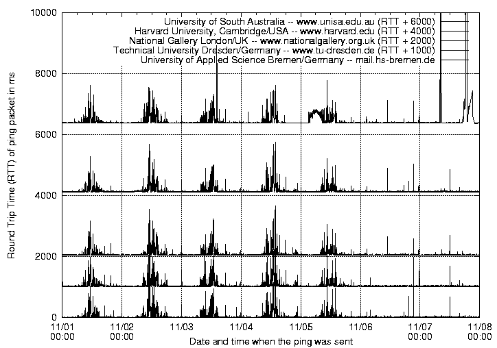
*) The 0-level of these graphs were shifted to a grid line.
The first expected result of this measurement was that the time delay depends on the distance to the destination. This can be seen in the average values (table on page 91) as well as in the first diagram on page 102. The minimum, average, and maximum values on each measurement increase with the distance. The graphs in the diagram represent this by being shifted higher according to the distance.
The second observation was that the time delay for all destinations increased to very high values from around 8am to about noon and decreases from noon to 7pm to “normal” values. All graphs are following almost the same pattern. It was assumed that there is a change in the time delay depending on the daytime. However, the increases should have been shifted by the time difference to the time zone of the destination if the destination was to causes a countable amount of the time delay.
All curves have almost the same shape. Because of this it was assumed that the same reason caused the time delay for all destinations. When translating this to network-language, it means that all pings went through the same sub-network. There is only one sub-network which matches this characteristic: the local school and university sub-network through which the server sending the pings is connected to the Internet. After this network the pings took different routes.
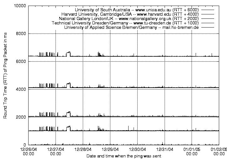
To proof this assumption, that the workload of local school and university network was causing the majority of the time delays, a second measurement was conducted. To exclude the possibility of high work loads this measurement was conducted during the holiday period.
In comparison to the first measurement the time delay is almost stable. Except of some peaks on Monday which might have been caused by network maintenance.
As a conclusion of the ping measurement it can be said that the Internet can be used for remote control quite well as long as some assumptions are made:
 |
 |
|
To test the basic functions (socket_bind() and socket_connect()) the test-program src/tests/test001sockets.c (appendices, section G.1 on page 181) was implemented. The function socket_accept() was tested by the program src/tests/test003block.c (appendices, section G.3 on page 181), please refer to section 4.3.2 (page 106).
The program test001sockets.c implements a server and a client to test the network-functions on the loop-back-network6 of the local machine. The server binds a port, receives one 8192-byte-block, inverts it, and sends it back. The client side connects to the server, sends a random-block, inverts it, receives a second block, and compares both. If both blocks (received and local inverted one) are equal it is assumed that the test was successful.
|
The test-program src/tests/test003block.c (appendices, section G.3 on page 181) which tests block transfer functions works in almost the same way as the test-program for the basic socket functions. Changes are: the program connects localhost and uses the block transfer functions to transfer blocks.
The server-side program uses and tests this functions (in the following order)
to receive a block. block_receive_send() is used to send this block back. The client side only uses block_receive_send() and block_receive_receive().
After these four tests are done, the authentication (functions socket_md5auth()) is tested as well. This is done by running one test and authenticating the connection before the block-transfer starts.
After some troubleshooting all functions worked properly. During the test 3 and 4 the error “recv(): Bad file descriptor” occurs because the thread still tries to receive after the client closes the connection. The thread will recognise (through this exception) if the connection is closed and terminate. This event is documented by the message “(server: connection terminated.)”, which was perceived during the test.
A small test-program src/tests/tes005realtime.c (appendices, section G.4 on page 182) which only implements the linemonitor-functions was used to test these functions. This program starts either the server or the client of the linemonitor-system depending on the parameters which were given:
The client needs to know which server on which port has to be connected, while the server only needs to know which port to bind (and wait for incoming connections). Please refer to section A.4 (page 160) for a description of the remaining parameters.
To test if the line monitor detects when the time-limit was exceeded, the quality of the line was lessened by overloading the connection with pings7 and by breaking the network connection trough unplugging it.
Before the hardware-interface was implemented the circuit was tested with MultiSIMTM 2001. The result of the simulation validated the results of the calculations in section 3.4.2 (page 75). This simulation used a substitution resistor (calculated as RL) to simulate the valve.
Table 5 lists the measurements which were conducted to test if the hardware was implemented properly.
|
The software-interface was tested by monitoring the bits of the parallel port. At this time the hardware-interface was not connected. After some troubleshooting the interface seemed to work properly.
To be able to run the final test on the entire interface a test-program (src/ example/test001interface.c) (appendices, section G.5 on page 182) was written. This program initialises the interface (interface_init()) first. After this it reads (x,y) coordinates from the keyboard and hands them over to the interface (interface_driveto()). After a few mistakes were eliminated the interface worked properly.
The major mistake in this phase of the development was a misinterpretation of the parameter of usleep()8. Milliseconds instead of microsecond were used. As mentioned earlier, the movements of the robot’s platform are not linear. For this reason the interface does not work accurately.
The implementation and the testing of the GUI were running almost at the same time. All newly included details were checked when they were ready. These tests were conducted by the author personally because there is no point in writing a test-program to test the interface to the user. The user has to decide if the interface works properly or not.
The GUI was implemented and tested in these steps:
All these steps are fully implemented now. The system works.
Addison, D. (2001) Embedded Linux applications: An overview
[Online] Available at
http://www-106.ibm.com/developerworks/linux/library/l-embl.html
(accessed 20. October 2004)
Andreu, D.; Fraisse, P.; Roqueta, V.; Zapata, R. (2003) Internet enhanced
teleoperation toward a remote supervised delay regulator IEEE International
Conference on Industrial Technology 10-12 December 2003 p663-668 volume 2 [Online]
Available at
http://0-ieeexplore.ieee.org.lispac.lsbu.ac.uk/iel5/9059/28746/
01290733.pdf (accessed 9. December 2004)
Ball, P.; Farnham, J; Iraca, S. (1999) Transmission Control Protocol/Internet
Protocol TCP/IP [Online] Available at
http://cne.gmu.edu/itcore/internet/tcpip/tcpip.html
(accessed 11. December 2004)
Belousov, I. (2004) Internet Robotics [Online] Available at
http://www.keldysh.ru/pages/i-robotics/operidea.html
(accessed 26. November 2004)
Berkeley Distribution (1996) Ping Manual Page [Online] Available at
http://snowhite.cis.uoguelph.ca/course_info/27420/ping.html
(accessed 12. November 2004)
Blandford, J; Clasen, M; Janik, T; Lillqvist, T; Quintero, F.M.; Rietveld,
K; Sandmann, S; Taylor, O; Wilhelmi, S (2005) GTK+ – The GIMP Toolkit
[Online] Available at
http://www.gtk.org/ (accessed 28. March 2005)
British Standard (1992) Industrial robots – Part 6: Recommendations for safety; BS
7228-6:1992; EN 775:1992; ISO 10218:1992 [Online] Available at
http://bsonline.techindex.co.uk/ (accessed 28. October 2004)
Chen, Y.-M.; Chen, Y.-B. (2004) Research reform on real-time operating system
based on Linux WCICA 2004. Fifth World Congress on Intelligent Control
and Automation 5-19. June 2004 p3916-3920 Volume 5 [Online] Available at
http://0-ieeexplore.ieee.org.lispac.lsbu.ac.uk/iel5/9294/29576/
01342230.pdf (accessed 20. October 2004)
Elhaji, I.; Tan, J.; Xi, N.; Fung, W.K.; Liu, Y.H.; Kaga, T.; Hasegawa, Y.;
Fukuda, T. (2000) Multi-site Internet-based cooperative control of robotic
operations. Proceedings 2000 IEEE/RSJ International Conference on Intelligent
Robots and Systems, 2, 31. Oct - 5. Nov 2000 p826-831 [Online] Available at
http://0-ieeexplore.ieee.org.lispac.lsbu.ac.uk/iel5/7177/19309/
00893121.pdf (accessed 20. October 2004)
Engelen, P. (2004) GTK-Drawing Demo on Win32 [Online] Available at
http://mail.gnome.org/archives/gtk-app-devel-list/2004-October/
msg00105.html (accessed 28. March 2005)
Fairhurst, G. (2004) Carrier Sense Multiple Access with Collision Detection
(CSMA/CD) [Online] Available at
http://www.erg.abdn.ac.uk/users/gorry/course/lan-pages/csma-cd.html
(accessed 11. December 2004)
Feibel, W. (1990) Using ANSI C in Unix. Berkeley: Osborne McGraw-Hill
Forouzan, B. A. (2001) Data Communication and Networking, 2nd edition. New York: McGraw-Hill.
Free Software Foundation (1999) GNU Lesser General Public License.
[Online] Available at
http://www.gnu.org/copyleft/lesser.html (accessed 28. March 2005)
Free Software Foundation (2004) The Free Software Definition
[Online] Available at
http://www.gnu.org/philosophy/free-sw.html (accessed 28. March 2005)
Gale, T.; Main, I. (2000) GTK+ 1.2 Tutorial: Chapter 25. Scribble, A Simple
Example Drawing Program [Online] Available at
http://www.johnmalone.org/gtk/tutorial/sec-eventhandling.html
(accessed 28. March 2005)
Guthrie, J (2004) Understanding GPS Coordinates [Online] Available at
http://www.co.lincoln.wa.us/GIS%20Data/Understanding%20GPS%20Coordi
nates.pdf (accessed 04. February 2005)
Han, K.-H.; Kim, S.; Kim, Y.-J.; Lee, S.-E.; Kim, J.-H. (2001) Implementation
of Internet-based personal robot with Internet control architecture. Proceedings 2001
ICRA. IEEE International Conference on Robotics and Automation 2001 p217-222
volume 1 [Online] Available at
http://0-ieeexplore.ieee.org.lispac.lsbu.ac.uk/iel5/7423/20179/
00932556.pdf (accessed 20. October 2004)
Hargreaves, S. (2004) Allegro – A game programming library.
[Online] Available at
http://www.talula.demon.co.uk/allegro/ (accessed 28. November 2004)
Heesch, D. (2004) Doxygen: Introduction [Online] Available at
http://www.stack.nl/ dimitri/doxygen/ (accessed 20. December 2004)
IBM Corporation (1995) TCP/IP Tutorial and Technical Overview: Ports and
Sockets [Online] Available at
http://www.auggy.mlnet.com/ibm/3376c210.html (accessed 22. December
2004)
Kennington, A (2000) Alan Kennington’s recommendations and suggestions [Online]
Available at
http://www.topology.org/reco/ (accessed 04. February 2005)
Kernighan, B. W.; Ritchie, D. M. (1988) The C Programming Language, 2nd edition. London: Prentice Hall ISBN 0-131-10362-8
Kozierok, C. M. (2004) The TCP/IP Guide [Online] Available at
http://www.tcpipguide.com/free/index.htm (accessed 12. November 2004)
Liu, P. X.; Meng, M.Q.-H.; Gu, J.; Yang, S.X.; Hu, C. (2003) Control and data
transmission for Internet robots Proceedings ICRA 2003. IEEE International
Conference on Robotics and Automation 14-19 September 2003 p1659-1664 volume 2
[Online] Available at
http://0-ieeexplore.ieee.org.lispac.lsbu.ac.uk/iel5/8794/27834/
01241832.pdf (accessed 21. October 2004)
Liu, Y.; Chen, C.; Meng, M. (2000) A study on the teleoperation of robot systems
via WWW Canadian Conference on Electrical and Computer Engineering 7-10. March
2000 p836-840 volume 2 [Online] Available at
http://0-ieeexplore.ieee.org.lispac.lsbu.ac.uk/iel5/6844/18402/
00849583.pdf (accessed 20. October 2004)
LRAV/AVDAY (1985) Computer in Control, 01: Introducing the Robot. [Video]
Maptech, Inc. (2005) Online Maps: Map Server [Online] Available at
http://mapserver.maptech.com/ (accessed 04. February 2005)
Mattis, P. (1998) The GIMP Toolkit (GTK Documentation) [Online] Available
http://www.csa.iisc.ernet.in/old-website/Department_Resources/
Hypertext/gtk/gtk_toc.html (accessed 28. March 2005)
McKerrow, P. J. (1991) Introduction to Robotics. Singapore: Addison-Wesley. ISBN: 0-201-18240-8
Messmer, H.-P.; Dembowski, K (2003) PC-Hardwarebuch (German: PC-Hardwarebook) 7th edition. Munich: Addison-Wesley. ISBN 3-827-32014-3.
Mitchell M.; Oldham J.; Samuel A. (2001) Advanced Linux Programming, New
Riders Publishing [Online] Available at
http://docs.linux.cz/programming/other/ALP/
advanced-linux-programming.pdf (accessed 20. December 2004)
Plauger, P.J.; Brodie, J. (1989) Standard C - A Reference. London: Prentice Hall. ISBN 0-134-36411-2
Postel, J. (1981) RFC 792 – Internet Control Message Protocol
[Online] Available at
http://www.freesoft.org/CIE/RFC/792/index.htm
(accessed 11. November 2004)
Sato, H.; Yakoh, T. (2000) A real-time communication mechanism for RTLinux
IECON 2000. 26th Annual Conference of the IEEE Industrial Electronics Society
22-28. October 2000 p2437-2442 volume 4 [Online] Available at
http://0-ieeexplore.ieee.org.lispac.lsbu.ac.uk/iel5/7662/20956/
00972379.pdf
(accessed 19. October 2004)
Schwarzenbach, J.; Gill, K.F. (1992) System Modelling and Control, 3rd edition. London: Edward Arnold. ISBN: 0-340-54379-5
Unknown (2004) TCL Developer Xchange: tcl/tk [Online] Available at
http://www.tcl.tk/software/tcltk/ (accessed 28. November 2004)
Wilson, G. (2001) OSI Model Layers [Online] Available at
http://www.geocities.com/SiliconValley/Monitor/3131/ne/osimodel.html
(accessed 11. December 2004)
This section compares
the planing of the project
with its actual realisation.
After the work breakdown
structure is given, the final
version of the Gantt char is
shown. This is followed
by the comparison of the
Gantt charts and action
plans from the beginning,
the middle, and the end
of the project. In the end
the milestones and some
explanations about the
project and it’s planning
are given.
|
 |
 |
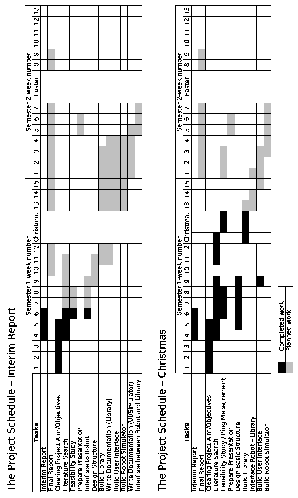
Action Plan Pre Interim Report
| Estimated Duration | |||
| Task | in Weeks | Precedence | |
| A | Interim Report | 3 | - |
| B | Final Report | 15 | Feedback A |
| C | Clearing Project Aim/Objectives | 5 | - |
| D | Literature Search | 8 | - |
| E | Feasibility Study | 3 | C |
| F | Prepare Presentation | 2 | C,(E) |
| G | Interface to Robot | 4 | C |
| H | Design Structure | 4 | C |
| I | Build Library | 8 | (G) |
| J | Write Documentation (Library) | 9 | (I) |
| K | Build User Interface | 7 | (I) |
| L | Build Robot Simulator | 7 | (I) |
| M | Write Documentation (UI/Simulator) | 5 | (K),(L) |
| N | Interface between Robot and Library | 3 | G,(M) |
Action Plan After Interim Report
| Estimated Duration | |||
| Task | in Weeks | Precedence | |
| A | Interim Report | 3 | - |
| B | Final Report | 8 | Feedback A |
| C | Clearing Project Aim/Objectives | 5 | - |
| D | Literature Search | 9 | - |
| E | Feasibility Study / Ping Measurement | 8 | C |
| F | Prepare Presentation | 2 | C,(E) |
| I | Build Library | 4 | C |
| K | Build User Interface | 5 | (I),(N) |
| L | Build Robot Simulator | 5 | (K) |
| N | Interface between Robot and Library | 3 | (I) |
 |
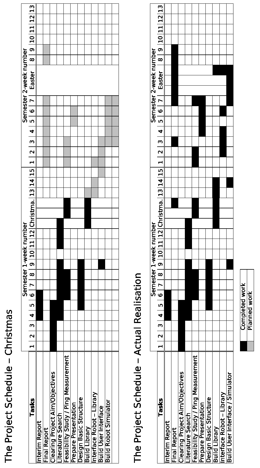
Action Plan After Interim Report
| Estimated Duration | |||
| Task | in Weeks | Precedence | |
| A | Interim Report | 3 | - |
| B | Final Report | 8 | Feedback A |
| C | Clearing Project Aim/Objectives | 5 | - |
| D | Literature Search | 9 | - |
| E | Feasibility Study / Ping Measurement | 8 | C |
| F | Prepare Presentation | 2 | C,(E) |
| I | Build Library | 4 | C |
| K | Build User Interface | 5 | (I),(N) |
| L | Build Robot Simulator | 5 | (K) |
| N | Interface between Robot and Library | 3 | (I) |
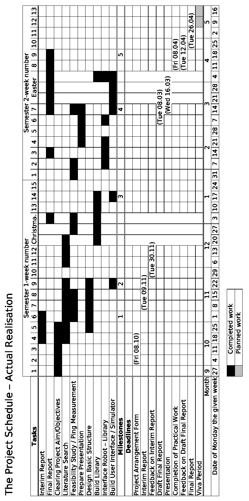
Final Action Plan
| Estimated Duration | |||
| Task | in Weeks | Precedence | |
| A | Interim Report | 3 | - |
| B | Final Report | 8 | Feedback A |
| C | Clearing Project Aim/Objectives | 5 | - |
| D | Literature Search | 9 | - |
| E | Feasibility Study / Ping Measurement | 8 | C |
| F | Prepare Presentation | 5 | C,(E) |
| I | Build Library | 6 | C |
| K | Build User Interface / Simulator | 6 | (I),(N) |
| N | Interface between Robot and Library | 5 | (I) |
 |
The milestones one and three were met. The last milestone will be also be met in time.
The milestones two and four were missed. As mentioned earlier the decision about the robot was delayed. This caused the missing of the second milestone. The fourth milestone was missed by almost three weeks because of the fact that the work was delayed by some neglected factors. The development of the interface to the robot was delayed. The time which was necessary to prepare the presentation was underestimated. And external events like exams interfered with the initial plan.
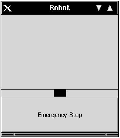
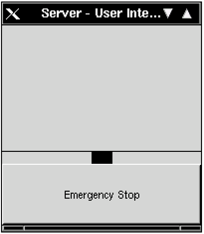
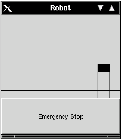
The robot is shown (simulated) in both programs. The black rectangle pictures the platform of the robot which can change its position.
The guirobot has to be started first. In the second step the guiserver connects to the guirobot. After this connection is established, the guirobot connects to the guiserver to monitor the stability and the speed of the line with the linemonitor(). Both programs are looking almost identical:
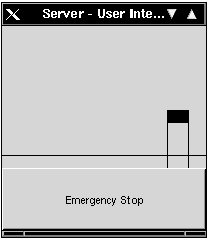
Their lookout (title line, buttons) depends on the used window manager and its configuration. In this case AfterStep is in use.
The difference between these two Graphical User Interfaces (GUIs) is that only the guiserver allows manipulations of the position of the robot’s platform. The guirobot shows the actual position and drives the platform of the robot to the required position if the interface is active and can access the hardware.
Click (with the left mouse-button) on the robot’s platform (sketched as black rectangle) and move it with held mouse button to the new position. Release the button. An example of the result of this can be seen in the following screenshot:
Both programs are able to stop all movements of the robot by clicking “Emergency Stop”. This emergency stop is also executed if the window is closed or the program receives a terminate signal.
In addition to this the linemonitor stops the robot if the the connection breaks down or if the server does not answer within a given time period.
As mentioned the guirobot has to be started first. This program receives the following parameters:
guirobot port-to-bind soft_msec hard_msec wait_msec
The interface initialises the robot. That means driving the robot’s platform to the (x=50,y=0) coordinates. The interface assumes that the robot is already in the position x=50. The x-position will not change. However, this takes some time. The program is ready when the window is displayed.
After the window is displayed the guiserver should be started with the following parameters:
guiserver robot-address port soft_msec hard_msec wait_msec
PDF Version (best view)
LaTeX SRC
Entire Project and Appendices
|
Pages by Andreas B. M. Hofmeier |
|
Impressum/Note Privacy |
|---|
|
http[s]://www.abmh.de/en/papers/lsbu/fyp/doc/FYPFinalReport.HTML/index.html |
|---|
 |
(c) Andreas B. M. Hofmeier This work is licensed under a Creative Commons Attribution-Noncommercial-Share Alike 3.0 Germany License |